- 您现在的位置:买卖IC网 > Sheet目录312 > AT24C11Y1-10YU-1.8 (Atmel)IC EEPROM 1KBIT 1MHZ 8MAP
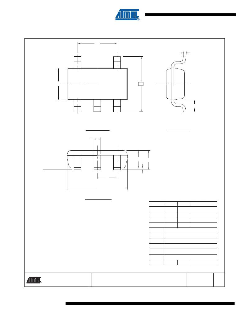
5TS1 – SOT23
e 1
E 1
5
4
E
C
C L
L 1
1
2
TOP VIEW
b
3
A 2
A
END VIEW
SEATING
PLANE
e
D
SIDE VIEW
A 1
COMMON DIMENSIONS
(Unit of Measure = mm)
1. Dimension D does not include mold flash, protrusions or gate burrs. Mold flash,
SYMBOL
MIN
NOM
MAX
NOTE
protrusions or gate burrs shall not exceed 0.15 mm per end. Dimension E1 does
not include interlead flash or protrusion. Interlead flash or protrusion shall not
exceed 0.15 mm per side.
A
A 1
-
0.00
- 1.10
- 0.10
2. The package top may be smaller than the package bottom. Dimensions D and E1
are determined at the outermost extremes of the plastic body exclusive of mold
flash, tie bar burrs, gate burrs and interlead flash, but including any mismatch
between the top and bottom of the plastic body.
3. These dimensions apply to the flat section of the lead between 0.08 mm and 0.15
mm from the lead tip.
4. Dimension "b" does not include dambar protrusion. Allowable dambar protrusion
shall be 0.08 mm total in excess of the "b" dimension at maximum material
condition. The dambar cannot be located on the lower radius of the foot. Minimum
space between protrusion and an adjacent lead shall not be less than 0.07 mm.
A 2
c
D
E
E 1
L 1
e
0.70
0.08
0.90 1.00
- 0.20
2.90 BSC
2.80 BSC
1.60 BSC
0.60 REF
0.95 BSC
3
1,2
1,2
1,2
e 1
1.90 BSC
This drawing is for general information only. Refer to
JEDEC Drawing MO-193, Variation AB for additional
information.
b
0.30 - 0.50
3,4
6/20/03
R
1150 E. Cheyenne Mtn. Blvd.
Colorado Springs, CO 80906
TITLE
5TS1, 5-lead, 1.60 mm Body, Plastic Thin Shrink
Small Outline Package (SHRINK SOT)
DRAWING NO.
PO5TS1
REV.
A
14
AT24C11
3409G–SEEPR–8/07
发布紧急采购,3分钟左右您将得到回复。
相关PDF资料
AT24C128BY6-YH-T
IC EEPROM 128KBIT 1MHZ 8DFN
AT24C128C-XHM-B
IC EEPROM 128KBIT 400KHZ 8TSSOP
AT24C128Y1-10YU-1.8
IC EEPROM 128KBIT 400KHZ 8MAP
AT24C164-10SU-1.8
IC EEPROM 16KBIT 1MHZ 8SOIC
AT24C16AY6-10YH-1.8
IC EEPROM 16KBIT 400KHZ 8DFN
AT24C16BY6-YH-T
IC EEPROM 16KBIT 1MHZ 8DFN
AT24C256BW-SH-T
IC EEPROM 256KBIT 1MHZ 8SOIC
AT24C256C-XHL-B
IC EEPROM 256KBIT IND 8TSSOP
相关代理商/技术参数
AT24C128
制造商:ATMEL 制造商全称:ATMEL Corporation 功能描述:2-Wire Serial EEPROMs
AT24C128_03
制造商:ATMEL 制造商全称:ATMEL Corporation 功能描述:2-wire Serial EEPROMs
AT24C128_06
制造商:ATMEL 制造商全称:ATMEL Corporation 功能描述:Two-wire Serial EEPROMs
AT24C128_07
制造商:ATMEL 制造商全称:ATMEL Corporation 功能描述:Two-wire Automotive Temperature Serial EEPROMs
AT24C128-10CC
制造商:ATMEL 制造商全称:ATMEL Corporation 功能描述:2-Wire Serial EEPROMs
AT24C128-10CC-1.8
制造商:ATMEL 制造商全称:ATMEL Corporation 功能描述:2-Wire Serial EEPROMs
AT24C128-10CC-2.7
制造商:ATMEL 制造商全称:ATMEL Corporation 功能描述:2-Wire Serial EEPROMs
AT24C128-10CI
制造商:ATMEL 制造商全称:ATMEL Corporation 功能描述:2-Wire Serial EEPROMs